.svg)
Below is the technical specs and data for the G5 Voodoo Neo 4 and 6 ECU’s
Connectors:
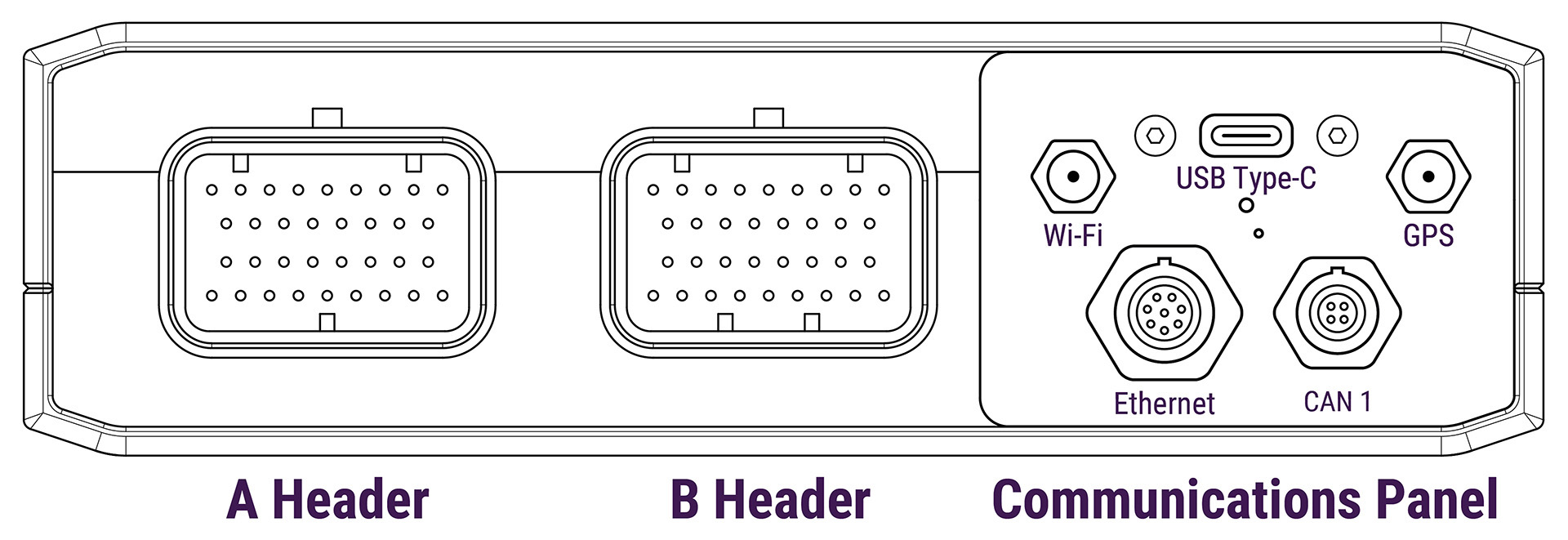
If you wish to make your own cables, the table bellow lists cable connector standards and part numbers where applicable. You can use the pinouts guide for more information on how to populate the connectors.
Also listed are relevant accessories for pre-made cables, pin kits, and antennas we have available to purchase through our dealer network.
|
ECU Connector |
Relevant Accessories |
Standard / Manufacturer Part No. |
|---|---|---|
|
A Header |
TE Superseal 1.0 |
|
|
B Header |
TE Superseal 1.0 |
|
|
Wi-Fi |
RP-SMA (reverse polarity) |
|
|
GPS |
|
SMA |
|
USB |
|
USB Type-C |
|
Ethernet |
|
Cat-5 10/100
|
|
CAN1 |
|
Cable connector: WEiPU SF610B/P4 |
Pin Specifications
|
Pin Functions |
Limits |
Pull-Up |
Fly-wheeled |
Details |
|---|---|---|---|---|
|
Trigger |
±60V (RMS) |
|
|
Reluctor, Proximity, Optical or Hall |
|
Knock |
50v Transient |
|
|
|
|
An Temp |
VBat |
Configurable 1k or 10k to 5v, or no pull-up |
|
|
|
An Volt |
VBat |
|
|
Only reads 0-5V Input |
|
Digital Input |
±60V (RMS) |
Configurable 4.7kΩ Pull-up to VBat |
|
Safe for use with reluctor sensors. |
|
ADIO |
5A Continuous
|
Configurable 1.5kΩ Pull-up to VBat |
Yes |
|
|
Ignition |
5A Continuous |
100Ω Pull-up to 8v |
Yes |
|
|
Injection 1-8 |
5A Continuous |
|
No |
Recommend external flywheel diode when using for Aux PWM
|
|
Injection 9-12 |
5A Continuous |
|
Yes when used as Aux |
|
|
Aux. 1-2 |
5A Continuous |
1.5kΩ Pull-up to VBat |
Yes |
|
|
Aux. 3-6 (H-Bridge) |
3A Continuous
|
|
Yes |
|
|
Aux. 7-12 |
5A Continuous |
100Ω Pull-up to 8v |
Yes |
|
|
CAN 1
|
3.6A Continuous |
|
|
Safe for use with Link CAN Lambda |
Dimensions: