Simple ECU Output Preset
Introduction
The Link Razor Power Distribution Module (PDM) is a software-configurable device that replaces traditional fuses and relays. Installing a Link Razor PDM can create cleaner wiring and give additional control that traditional fuses and relays do not have. Link Razor PDMs can be complex to set up so, to simplify the process, base configurations have been created for common PDM installations.
This example uses all of the user configurable pins of the PDM as outputs. In a sense, the PDM acts like a collection of relays connecting these output pins to battery power. The “relays” or outputs are controlled by the CAN Auxiliary outputs on the ecu.
In this article, you’ll find a list of what you’ll need, how to load this Preset onto your Razor PDM, how you’ll wire this Preset up, and lastly, more technical information should you need it, such as current limits, and explanations around the logic programmed into this Preset.
Bill Of Materials
Component | Amount | Location |
|---|---|---|
Link ECU | 1 | |
Link Razor PDM | 1 | |
Link Razor PDM Configuration | 1 | |
Link ECU Configuration | 1 | |
Link ECU Layout | 1 | |
USB A to USB C Cable | 1 | Comes with Razor PDM |
Wiring Diagram & Pinout

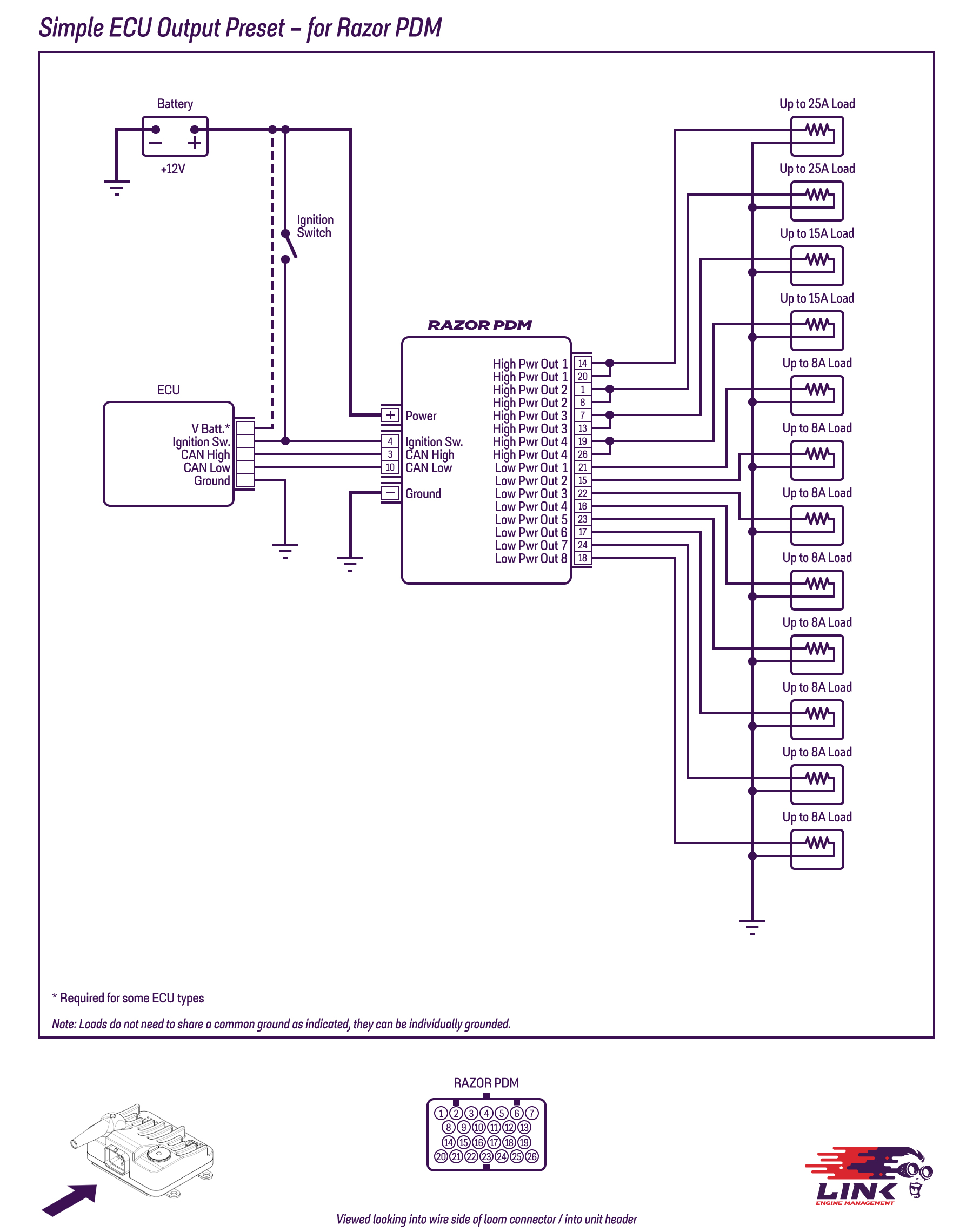
Figure 1 - Wiring diagram for the Simple ECU Output Preset for Razor PDM
The V-Batt line of the wiring diagram can be fitted when using a G5 Voodoo Pro but isn’t required. Check the pinout of your purchased Link ECU for more details.

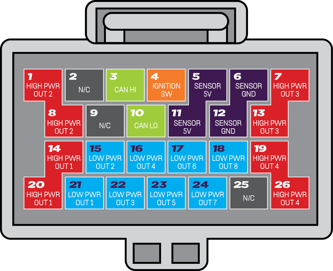
Figure 2 - Pinout for the Simple ECU Output Preset for Razor PDM
Loading the Preset Configuration
Ensure your PDM is up to date by following the steps outlined here
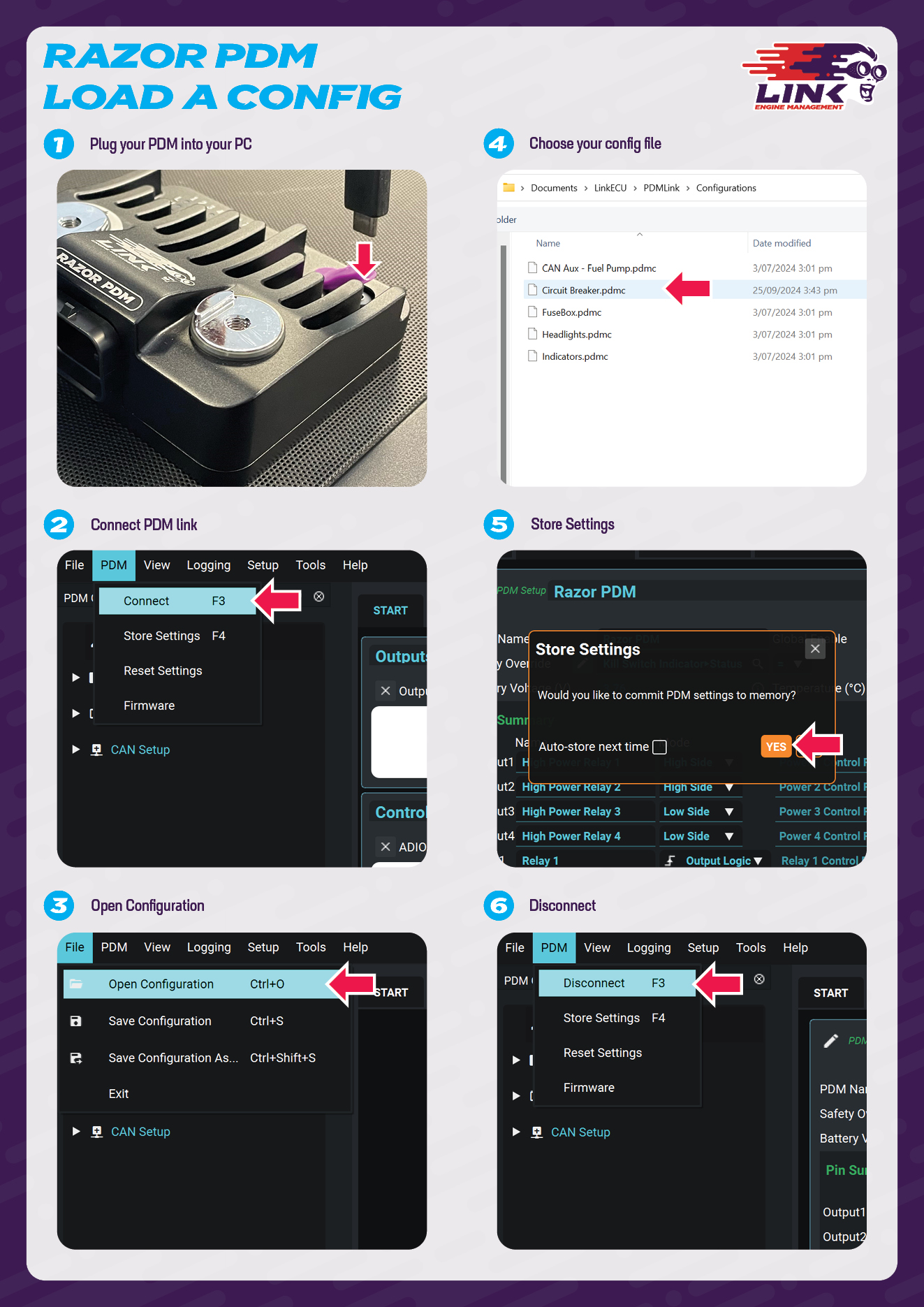
By default, the Link Razor PDM comes with a blank configuration and needs to have either a configuration loaded onto it or a new configuration setup from the blank one. The configuration file for this example can be found in the bill of materials section above. Once your chosen Preset is downloaded, you can load this file into the PDM following the instruction set below.
The configs are normally kept in your PDMLink folder, under Configurations, but you can save them anywhere you choose.

Connect the Link Razor PDM to a computer via the supplied USB C to USB A cable. Note the PDM does not need to be wired into any external power for this step and can be configured purely over USB power.
Open PDMLink and click PDM > Connect, or press F3
Once the PDM has connected, click File > Open Configuration, or Ctrl+O
Navigate to the directory that you saved the Preset to, and select it.
When the app prompts you to store the data on the device, select ‘Yes’.
Disconnect the PDM from the app and PC.
Feel free to review the Preset configuration in PDMLink before disconnecting. You can use Presets as they are or as a starting point, customising them with your own logic and automation to meet your specific needs.
Generic CAN Aux Expander Setup Information
The example configuration supplied is set up to automatically take CAN data from the ECU and turn on the output pins in response. This means that the ECU is in complete control over the output of the pins unless safety limits like excess current draw are triggered.
For the ECU to communicate with the PDM over CAN, the setups for both devices need to match. In this example both devices are set to communicate over ID 500, but the devices actually use two CAN IDs to communicate. The PDM receives the requested output statuses from the ECU on ID 500 and sends its own physical IO statuses back to the ECU as feedback on CAN ID 501 (PDM IO statuses are always sent on ECU CAN ID +1). The CAN messages and IDs are further clarified in the table below.
CAN Messages Description
CAN ID | Frequency of Transmission | Information Sent in Message | Device Sending Message |
|---|---|---|---|
XXX (500 in this configuration) | 20Hz | Output controls | ECU |
XXX + 1 (501 in this configuration) | 20Hz | IO statuses | PDM |
More information on the ECU and PDM CAN communication system can be found in the help manual here. If a conflict occurs on the CAN Bus due to the CAN IDs 500 and 501. The CAN settings should changed via the Configuration page of the PDM layout and in the CAN Setup window in PCLink.
The PDM output protections are set as shown in the table below, these values can be changed to suit your application (e.g. A fuel pump’s protection values may be different from an engine fan’s). Each output’s protection settings are found on the corresponding tab for that output.
Output Specifications
Relay Name (Number) | Type | Inrush Limit (A) | Inrush Trip Time (s) | Inrush Duration (s) | Overcurrent Limit (A) | Overcurrent Trip Time (s) | Retry Limit | Retry Delay (s) | Temperature Limit (°C) |
|---|---|---|---|---|---|---|---|---|---|
1 | High Power | 60 | 0.5 | 2 | 25 | 2 | 5 | 1 | 90 |
2 | High Power | 60 | 0.5 | 2 | 25 | 2 | 5 | 1 | 90 |
3 | High Power | 25 | 0.5 | 2 | 15 | 2 | 5 | 1 | 90 |
4 | High Power | 25 | 0.5 | 2 | 15 | 2 | 5 | 1 | 90 |
5 | Low Power | X* | X* | X* | 8** | 2 | 5 | 1 | 90 |
6 | Low Power | X* | X* | X* | 8** | 2 | 5 | 1 | 90 |
7 | Low Power | X* | X* | X* | 8** | 2 | 5 | 1 | 90 |
8 | Low Power | X* | X* | X* | 8** | 2 | 5 | 1 | 90 |
9 | Low Power | X* | X* | X* | 8** | 2 | 5 | 1 | 90 |
10 | Low Power | X* | X* | X* | 8** | 2 | 5 | 1 | 90 |
11 | Low Power | X* | X* | X* | 8** | 2 | 5 | 1 | 90 |
12 | Low Power | X* | X* | X* | 8** | 2 | 5 | 1 | 90 |
*These values aren’t applicable for ADIO outputs
**The Overcurrent limits cannot be configured for low power IO.
Inrush Current
When some loads are initially turned on, they require much more current than normal. To handle this issue, High-Power outputs have a higher current limit of X.XA for the first 2 seconds of use. During this time, the output is not allowed to go over the increased current limit for more than 0.5 seconds. If it does, the output will turn off and go into a fault state. After 2 seconds of operation, the output will use the lower overcurrent limit of X A.
Continuous Current
The continuous overcurrent limits for output are shown in Table 2. All outputs' continuous overcurrent limits can be exceeded for 2 seconds. Afterwards, if the output still detects an overcurrent, it will go into a fault state. See Table 2 for further details on High-Power output specifications.
Fault Recovery
After going into a fault for 1 second, the output will automatically try to turn itself back on again. If an output faults 5 times, it will turn itself off until reset manually by the user. Turning the output off with the keypad will reset its fault count, allowing it to function as normal again.
Temperature Limit
Each output is configured to turn itself off when the board gets hotter than 90˚C to avoid damage to the device. The relay will go into a fault state, just like when it exceeds the current limit. However, the relay will not turn back on until the device’s temperature falls to 88˚C. For optimal thermal performance, it is recommended to keep the Link Razor PDM in an area with airflow and mounted to a large flat metallic surface.
Configuring the ECU
The ECU also needs to be configured to both control what the outputs do and send this information to the PDM. An example ECU configuration can be found in the bill of materials section of this page with a sample PCLink Layout. The sample configuration includes the CAN Communication with the PDM, with 8 of the PDM outputs being controlled by GP Outputs in the ECU (switched on/off functionality) and the remaining 4 outputs being controlled by GP PWM functions (PWM with configurable Frequency and Duty Cycle).
This sample map is designed to give insight into the setup of the ECU; to communicate with and control a PDM. If the sample MAP does get used in an application, a tune is necessary to run an engine. The key parts of the ECU sample configuration are the CAN Setup and the use of CAN Aux outputs instead of regular ECU outputs. All of the PWM output's characteristics of the PDM (On/Off state, frequency and duty cycle) are controlled by the ECU configuration.
The Generic ECU CAN Aux Expander PDM preset can be utilized without the use of the ECU map. The Razor PDM CAN setup configures the ECU such that each CAN Aux controls a PDM Output. Shown in the table below.
ECU CAN Aux Output | PDM Output |
|---|---|
CAN Aux 1 | High Power 1 |
CAN Aux 2 | High Power 2 |
CAN Aux 3 | High Power 3 |
CAN Aux 4 | High Power 4 |
CAN Aux 5 | PWM 1 |
CAN Aux 6 | PWM 2 |
CAN Aux 7 | PWM 3 |
CAN Aux 8 | PWM 4 |
CAN Aux 9 | Relay 1 |
CAN Aux 10 | Relay 2 |
CAN Aux 11 | Relay 3 |
CAN Aux 12 | Relay 4 |
The ECU MAP, can be further configured to make use of other control functions such as the 'Fuel Pump Control'. Note not all PDM pins can do PWM output functionality.
Further information on how to configure a Link ECU or PDM and what each setting does can be found in the PCLink Help manual for ECUs and in the PDM Help Manual for PDMs. Additional support and contact information is available on the product support page here.
.svg)