Simple CAN Keypad Preset
Introduction
The Link Razor Power Distribution Module (PDM) is a software-configurable device that replaces traditional fuses and relays. Installing a Link Razor PDM can create cleaner wiring and give additional control that traditional fuses and relays do not have. Link Razor PDMs can be complex to set up so, to simplify the process, base configurations have been created for common PDM installations.
This manual describes the behaviour of a Link Razor PDM when installed as a generic, CAN Keypad controlled relay box. Each button on a Link CAN Keypad is used to control a corresponding output of the PDM like a relay. Razor PDM outputs are capable of pulling up to +12V, down to ground, or even PWM switching between the two. In this configuration, all the outputs can be thought of as high-side relays that pull up to battery power when switched on. Throughout this document, the words “relay“ and “output“ are practically interchangeable.
The required hardware, wiring, and configuration are all explained with supporting diagrams. If the wiring diagram is followed exactly, the PDM and keypad will work without additional configuration. It is also possible to adjust the behaviour of an output to suit your specific application.
Bill of Materials
Component | Amount | Location |
|---|---|---|
Link Razor PDM | x1 | |
Link Engine Management 12 Button CAN Keypad | x1 | |
Link Razor PDM Configuration | x1 | |
PC with Windows 10 or 11 | x1 |
|
USB A to USB C Cable | x1 | Comes with Razor PDM |
Wiring Diagram & Pinout
The diagram below (Figure 1) shows how to wire electrical loads and the CAN keypad to the Link Razor PDM. In this configuration, all the smart relays output battery voltage when active. Connected loads need to be active-high in order to turn on when the output state is active. The keypad is connected to the same ignition switch line as the PDM so that they turn on at the same time. The pinout of the Razor PDM is shown in Figure 2. Note that outputs 1 - 4 are ‘high-power' while outputs 5 - 12 are 'low-power’.
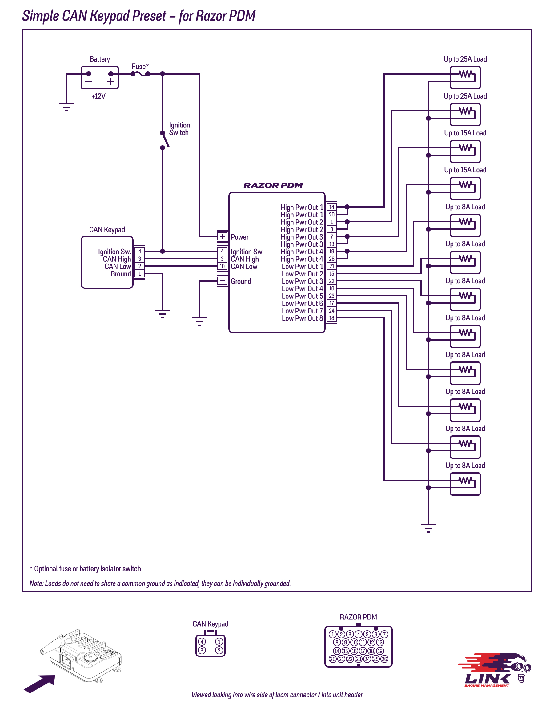
Figure 1 - Wiring diagram for Simple CAN Keypad Preset for Razor PDM
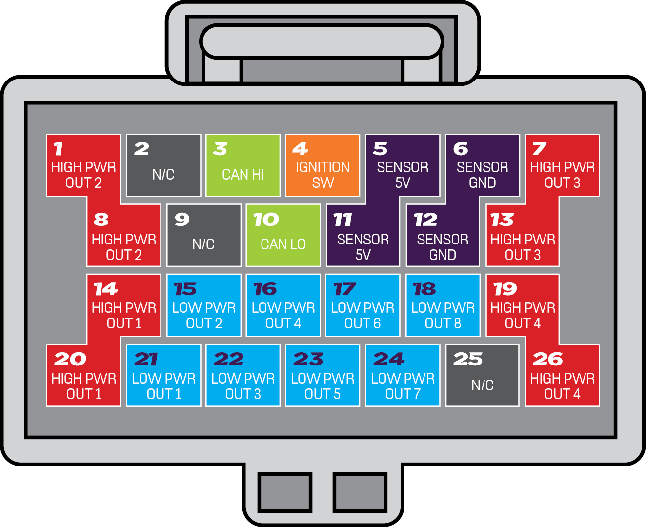
Figure 2 - Pinout for Simple CAN Keypad Preset for Razor PDM
Loading the Preset Configuration
Ensure your PDM is up to date by following the steps outlined here
By default, the Link Razor PDM comes with a blank configuration and needs to have either a configuration loaded onto it or a new configuration setup from the blank one. The configuration file for this example can be found in the bill of materials section above. Once your chosen Preset is downloaded, you can load this file into the PDM following the instruction set below.
The configs are normally kept in your PDMLink folder, under Configurations, but you can save them anywhere you choose.
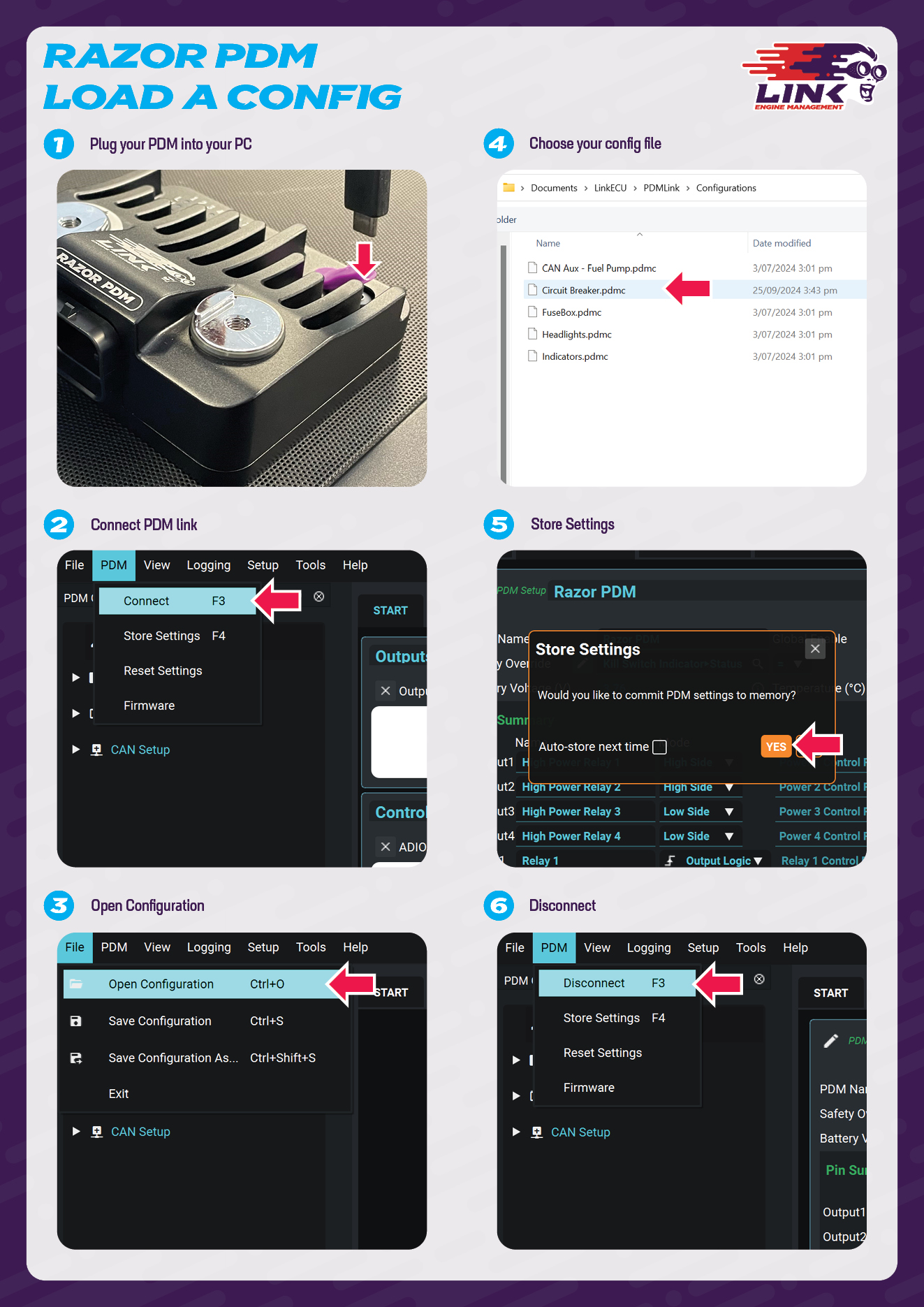
Connect the Link Razor PDM to a computer via the supplied USB C to USB A cable. Note the PDM does not need to be wired into any external power for this step and can be configured purely over USB power.
Open PDMLink and click PDM > Connect, or press F3
Once the PDM has connected, click File > Open Configuration, or Ctrl+O
Navigate to the directory that you saved the Preset to, and select it.
When the app prompts you to store the data on the device, select ‘Yes’.
Disconnect the PDM from the app and PC.
Feel free to review the Preset configuration in PDMLink before disconnecting. You can use Presets as they are or as a starting point, customising them with your own logic and automation to meet your specific needs.
Configuration Information
This section should act as a guide on how to use the Generic CAN Relay configuration. The functionality of the system, including that of the PDM Outputs and Keypad, is described below.
With this configuration, the Link Razor PDM has been set-up in such a way that each output reacts to a specific keypad button. Pressing a keypad button will turn a corresponding output either on or off. The figure below shows which output is connected to which keypad button. Each button is connected to the output that shares the same number e.g., Button 1 is connected to Output 1, Button 2 is connected to Output 2 etc.
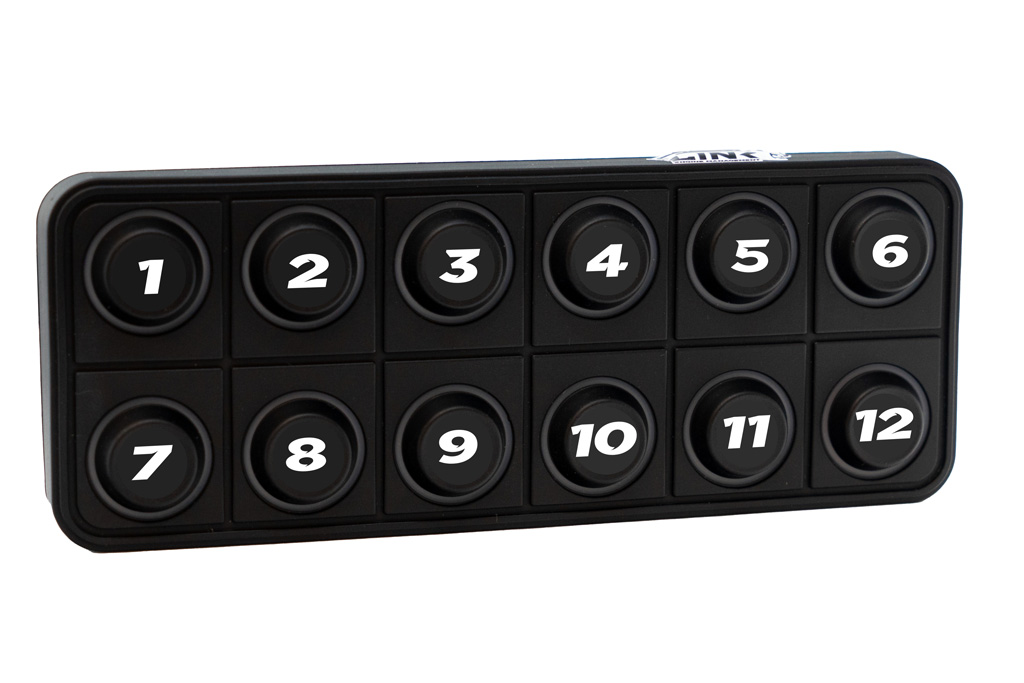
Figure 3 - Link CAN Keypad with Button and Output Numbers
Output Behaviour
The Generic CAN Relay box acts like a smart box of relays that are controlled by a CAN keypad. At start-up all the outputs are, by default, turned off and the corresponding keypad buttons blue (meaning inactive). Pressing a button once will turn the output on and make the button green (meaning active). When active, the output will switch to battery voltage and source current to the load. Pressing the button once more will turn the output off again and the button will return to blue. The control logic of each output follows the state diagram in Figure 3.
Every relay will work as previously described unless the current exceeds the relay’s rating. In this case, the relay will go into a fault state, turn its output off, and make the keypad button red. In-depth overcurrent behaviour is detailed in the Output Specifications section.
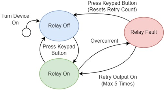
Figure 4 - State Diagram of a CAN Controlled Relay Output
Output Specifications
Relay (Output) | Type | Inrush Limit (A) | Inrush Trip Time (s) | Inrush Duration (s) | Overcurrent Limit (A) | Overcurrent Trip Time (s) | Retry Limit | Retry Delay (s) | Temperature Limit (˚C) |
|---|---|---|---|---|---|---|---|---|---|
1 | High-Power | 50 | 0.3 | 2 | 25 | 2 | 5 | 1 | 95 |
2 | High-Power | 50 | 0.3 | 2 | 25 | 2 | 5 | 1 | 95 |
3 | High-Power | 30 | 0.5 | 2 | 15 | 2 | 5 | 1 | 95 |
4 | High-Power | 30 | 0.5 | 2 | 15 | 2 | 5 | 1 | 95 |
5 | Low-Power | X | X | X | 8 | 2 | 5 | 1 | 95 |
6 | Low-Power | X | X | X | 8 | 2 | 5 | 1 | 95 |
7 | Low-Power | X | X | X | 8 | 2 | 5 | 1 | 95 |
8 | Low-Power | X | X | X | 8 | 2 | 5 | 1 | 95 |
9 | Low-Power | X | X | X | 8 | 2 | 5 | 1 | 95 |
10 | Low-Power | X | X | X | 8 | 2 | 5 | 1 | 95 |
11 | Low-Power | X | X | X | 8 | 2 | 5 | 1 | 95 |
12 | Low-Power | X | X | X | 8 | 2 | 5 | 1 | 95 |
Inrush Current
When some loads are initially turned on, they require much more current than normal. To handle this issue, High-Power outputs have a higher current limit of X.XA for the first 2 seconds of use. During this time, the output is not allowed to go over the increased current limit for more than 0.5 seconds. If it does, the output will turn off and go into a fault state. After 2 seconds of operation, the output will use the lower overcurrent limit of X A.
Continuous Current
The continuous overcurrent limits for output are shown in Table 2. All outputs' continuous overcurrent limits can be exceeded for 2 seconds. Afterwards, if the output still detects an overcurrent, it will go into a fault state. See Table 2 for further details on High-Power output specifications.
Fault Recovery
After going into a fault for 1 second, the output will automatically try to turn itself back on again. If an output faults 5 times, it will turn itself off until reset manually by the user. Turning the output off with the keypad will reset its fault count, allowing it to function as normal again.
Temperature Limit
Each output is configured to turn itself off when the board gets hotter than 90˚C to avoid damage to the device. The relay will go into a fault state, just like when it exceeds the current limit. However, the relay will not turn back on until the device’s temperature falls to 88˚C. For optimal thermal performance, it is recommended to keep the Link Razor PDM in an area with airflow and mounted to a large flat metallic surface.
Keypad Configuration
For this configuration, a 12-button Link CAN Keypad should be used if you wish to use all relays. Link keypads with fewer buttons will also work but some low-power relays will be unusable. Button numbers will still connect to the Relay with the same number e.g Button 1 will connect to Relay 1. Relays connected to whichever buttons are missing will be unusable without customising the configuration.
The Keypad communicates with the PDM over the CAN protocol which requires an ID for every device on the bus. Make sure there is nothing else on the CAN bus with the same value as the keypad to avoid conflicts. The CAN setup information is desrcibed in the table below.
Keypad CAN Channel Settings
CAN ID | 405 |
|---|---|
ID Format | Standard |
Frequency of Transmission (Hz) | 20 |
CAN Bus Data Rate (bps) | 1M |
Each button on the keypad acts like a latching switch: pressing the button once will turn it on and it will stay on until the button is pressed a second time. The buttons have LEDs behind them that indicate what state the output is in. These stateuses are described in the table below for reference. Note that, in this configuration, the Off status will only be seen if the PDM has no power, the keypad has no power, or the ignition line is low.
Keypad Button Colours
Output Status | Button Colour |
|---|---|
Inactive | Blue |
Active | Green |
Off | No Colour |
Fault | Red |
Further information on each setting and how to configure a Link PDM can be found in the PDM Help Manual . Additional support and contact information is available on the product support page here.
.svg)