CAN Functions
Setup
Setting a channel to the CAN Function mode allows the PDM to receive Status, Frequency and Duty cycle settings for an Output. To use all of the CAN Functions, just set one CAN Channel to the CAN Function Mode. Any Output can be used with any CAN Function. The easiest way to use CAN Functions is with a Link ECU but any device capable of transmitting over CAN can be used.
CAN Function Configuration

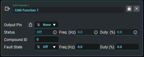
Output Pin | The Output pin directly controlled by this CAN Function. If an Output is selected in this list, its Status, Frequency and Duty Cycle will change according to the received values. Alternatively, you can feed the received CAN values (Status, Freq, Duty) into other functions such as Math Blocks or PID control. |
Status | Status value received from the incoming CAN message. Inactive=0, Active=1, Off=2, Fault=3 |
Frequency | Frequency value received from the incoming CAN message. |
Duty Cycle | Duty Cycle value received from the incoming CAN message. |
Compound ID | The Compound ID in the first byte, used to choose which frame in the CAN stream to use. For example, the Link ECU PDM CAN stream will send CAN Aux 1 information with a compound ID of 0. |
Fault State | State the CAN Function will change to if a CAN message has not been received for 2 seconds (and at least one has been received since power up). |
Fault Frequency | Frequency the CAN Function will change to if a CAN message has not been received for 2 seconds (and at least one has been received since power up). |
Fault Duty Cycle | Duty Cycle the CAN Function will go to if a CAN message has not been received for 2 seconds (and at least one has been received since power up). |
To setup the Link Razor PDM to receive the CAN Aux information:
Open PDMLink and connect to the PDM (F3 or PDM dropdown menu -> Connect).
Open CAN Setup -> Basic CAN Configuration
Configure the Bit Rate to match the ECU (Often 1 Mbit/s).
Open CAN Setup -> CAN Channels.
Select a spare CAN channel.
Select 'CAN Function' from the Mode drop-down menu.
Set the CAN ID to match the 'Link Razor PDM' Id in the ECU CAN Setup.
Set the Transmit Rate to None, this Mode only receive's data from the ECU and doesn't transmit any data.
Make sure a Store (F4) is performed.
Further setup is required in PDMLink to assign CAN Aux's from the ECU to CAN Function's in the Razor PDM before they can be used to control outputs. See GP Functions.
To setup the Link Razor PDM to transmit Pin Status and Current flow information to a Link ECU:
Open PDMLink and connect to the PDM (F3 or PDM dropdown menu -> Connect).
Open CAN Setup -> Basic CAN Configuration
Configure the Bit Rate to match the ECU (Often 1 Mbit/s).
Open CAN Setup -> CAN Channels.
Select a spare CAN channel.
Select 'IO Status Stream' from the Mode drop-down menu.
Set the CAN ID the ECU's 'Link Razor PDM' Id +1 if this PDM 1 in the ECU, +3 if this is PDM 2 in the ECU, +5 if this is PDM 3 in the ECU or +7 if this is PDM 4 in the ECU (e.g. if the ECU's 'Generic PDM' Id is 500 use Id 501 for PDM 1, Id 503 for PDM 2, Id 505 for PDM 3 or Id 507 for PDM 4).
Set the Transmit Rate to 20Hz, faster or slower rates can be used if desired.
Make sure a Store (F4) is performed.
Current and pin status information should now show up in the ECU, these runtime values and statuses are explained more in the ECU Helpfile.
To setup the Link Razor PDM to transmit CAN Keypad states and values to a Link ECU:
Open PDMLink and connect to the PDM (F3 or PDM dropdown menu -> Connect).
Open CAN Setup -> Basic CAN Configuration
Configure the Bit Rate to match the ECU (Often 1 Mbit/s).
Open CAN Setup -> CAN Channels.
Select a spare CAN channel.
Select 'Keypad Counts' from the Mode drop-down menu.
Set the CAN ID the ECU's 'Link Razor PDM' Id +2 if this PDM 1 in the ECU, +4 if this is PDM 2 in the ECU, +6 if this is PDM 3 in the ECU or +8 if this is PDM 4 in the ECU (e.g. if the ECU's 'Generic PDM' Id is 500 use Id 502 for PDM 1, Id 504 for PDM 2, Id 506 for PDM 3 or Id 508 for PDM 4).
Set the Transmit Rate to 20Hz, faster or slower rates can be used if desired.
Make sure a Store (F4) is performed.
The PDM's keypad data can now be used via CAN DIs or CAN Analog inputs as selected in the PDM's Keypad function settings.
.svg)