CAN Setup
The Razor PDM can communicate directly with any current Link ECU and with up to 3 other Razor PDMs. Third party ECUs can be configured to communicate with a Razor PDM using the CAN Streams outlined below.
ECU Setup
When connecting to a Link ECU, set up the ECU CAN as per the PCLink helpfile. G4X ECU Tuning Functions > CAN > Link Razor PDM
Ensure the latest version of PCLink is being used (V6.23 or later) and ensure the latest firmware has been installed.
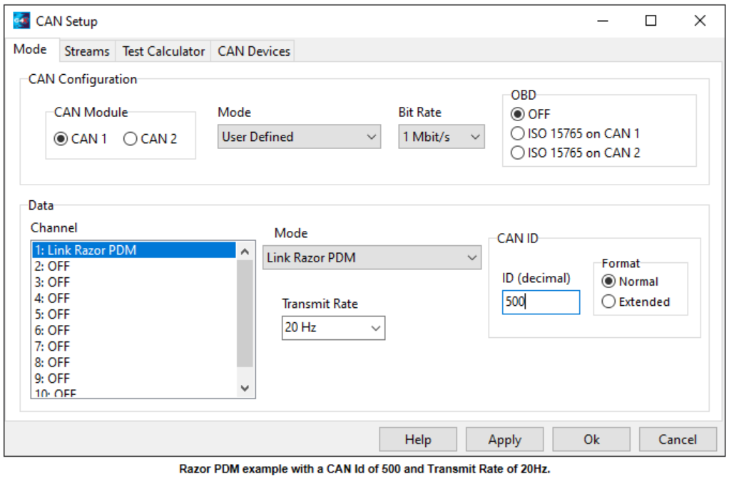
Select User Defined and in one of the channels select Link Razor PDM.
Choose an ID that is not being used and a transmit rate.
CAN Bus ID is in Decimal format.
There will be 5 IDs used. The one chosen and the four consecutive numbers following that ID.
ID = ECU transmit, ID + 1 = PDM1 IO Status, ID + 2 = PDM1 Keypad Counts, ID + 3 = PDM2 IO Status, ID + 4 = PDM2 Keypad Counts. This allows for up to 2 PDMs connected to the same Link ECU.
12 new runtimes (6 per PDM) have been added for currents, fault flags and status flags received by the ECU from the PDM.
CAN Aux 1 -16 are used to control the outputs on the PDM.
To setup a Link ECU to transmit the CAN Aux runtimes and receive basic PDM data:
Open the CAN Setup window (PCLink > ECU Controls > CAN Setup).
Select the CAN module to be used
Set the Mode to 'User Defined'.
Configure the Bit Rate to the same Bit Rate as the PDM (Often 1 Mbit/s).
Select a spare CAN channel
Select 'Link Razor PDM' from the Mode drop-down menu.
Set the CAN ID to an appropriate spare Id, the selected ID doesn't matter as long as the PDM is set to match and the next 4 CAN Ids are free (e.g. if Id 500 is used 501 to 504 must also be free and unused).
Set the Transmit Rate to 20Hz, this controls the rate at which the CAN Aux information is transmitted by the ECU, faster or slower rates can be used if desired.

Click Apply and then OK.
Make sure a Store (F4) is performed.
To setup a Link ECU to use one or more of the Razor PDM's ADIO channels or Keypad Functions as an ECU CAN input:
In PCLink connect to the ECU and open CAN -> PDM 1 in the ECU settings menu (or PDM 2, PDM 3 or PDM 4 depending on which PDM the input is coming from).
Select the appropriate ADIO or Keypad Function's setting and set it to an unused CAN Freq, CAN An or CAN DI input.
If all of the above CAN setups have been done correctly the selected CAN input should now show the status or value of the ADIO or Keypad function.
Note: Only ADIO 5-8 can be used as Frequency inputs.
Note: For CAN Keypad Functions a value of 1 or more is considered active when a CAN DI is selected.
PDM Setup
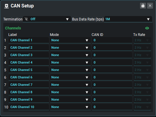
CAN Setup Configuration

Termination | Turns the PDM's terminating resistor On/Off. |
Bus Data Rate | Sets the data rate of the PDM CAN bus. The data rate needs to be the same on all devices connected to the same bus. |
Multi-PDM Quick Setup
Click on the pencil icon next to the PDM number dropdown to open the Quick Setup dialogue box. The quick setup box is designed to quickly and easily set up a system with an external device and multiple PDM’s.
NOTE: The Multi-PDM Quick setup box will reset all channels with the modes required for the CAN setup system.
Parameter | Description |
|---|---|
Base Id | The ID to base the rest of the system off. This ID is the same as the ECU CAN Id. |
Keypad Tx | The ID to receive Keypad counts from. |
Number Of PDMs | The number of PDMs in the system |
PDM Number | The PDM number in the system. These numbers are relative. So the ID’s of PDM 2 will be greater than PDM 1 and less than PDM 3. |
The quick setup dialogue sets the mode, can ID’s and transmission rates on the CAN Channels depending on the options selected in the quick setup box. These modes include the IO Status transmission, Keypad Counts transmission, Keypad counts reception, PDM1 IO Status reception, PDM2 IO Status reception, PDM3 IO Status Reception.
The system will have every PDM receive the other IO statuses of all other PDM’s in the system. Each PDM in the system will also have a CAN ID for the reception of keypad counts. This value is set in the dialogue box. The reception of keypad counts can be differ between PDM’s, For example PDM 2 can receive PDM 3’s Keypad counts and have PDM 1 receive PDM 2’s keypad counts and have PDM 4 receive PDM 1’s keypad counts.
The PDM Number in the quick setup window is different than the “PDM Rx IO status number”. This is because of the referential nature of the PDM RX IO Status. When you have PDM 1 it will receive IO Statuses from PDM 2, 3 and 4 however in the Channels they will be setup as PDM 1, 2 and 3.
The “Number of PDMs” value configures the extra CAN id’s needed for the IO status reception of the other PDM’s in the system.
NOTE: Ensure the Number of PDMs is always higher or the same as the PDM Number,
CAN Channel Setup
This is the starting point when setting up CAN on the Razor PDM. Currently, these channels can be used to receive or transmit, depending on the Mode, CAN streams that are detailed below.
Label | Whatever you wish to call each CAN Channel. By default they are set as CAN Channel 1 - 10. |
Mode | Sets the CAN Channel Mode:
|
CAN ID | The CAN ID the channel will send every message on |
Transmit Rate | How often the PDM will transmit the chosen message(s). This option is not required for receive steams. |
.svg)