Configuration
Software and Firmware
PDM Link software can be downloaded at linkecu.com/software-support/. Keep checking for updates to ensure you're using the latest release.
Firmware comes bundled with the PDMLink application - it can be accessed in the default location
To update firmware on the PDM, ensure you have downloaded the latest PDM Link software and installed this on your PC, the software contains the latest firmware.
The Software and Firmware versions can be found by selecting Menu>Help>About.
Connect the PDM to a PC using the supplied USB-C cable
Select Menu>PDM>Firmware
Click the 3 dot icon, and navigate to:
C:\Program Files (x86)\PDMLink\Resources\Firmware\firmware_package_1.X.XXX.lfp
Select the latest version and select Open. This will populate the Upgrade Firmware menu with all versions in the folder
Highlight the latest version and select START
Basic Configuration
Selecting View>PDM Configuration will produce the configuration tree on the left-hand side of the page.
The Basic Configuration tab contains the following settings:
PDM Name. If more than one PDM is being used this is where the user identifies them for later configuration.
PDM Output Enable. This setting is a temporary override that disables all high and low power outputs, while still allowing them to be configured in software.
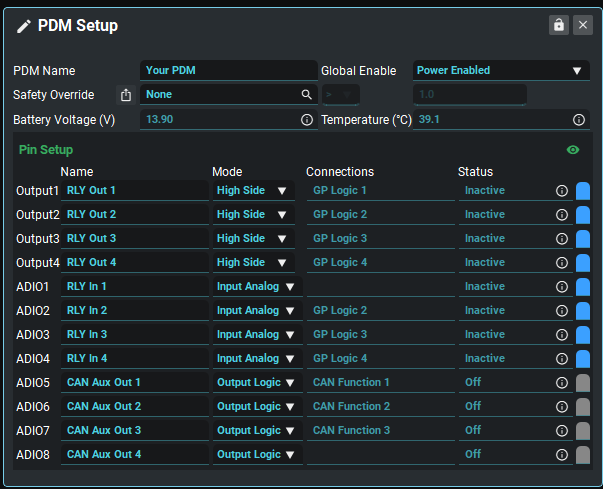
PDM Setup
This provides a top level overview of the current PDM setup, pin configuration and, status.
Each PDM can be given friendly name
Each pin can be set to one of the various modes supported by that pin type.
Once the pin modes have been defined they will be available in the respective menus, Outputs Pins or Input Pins, for setup.
Once a pin has been configured all usages of the pin can be seen in the Connections box
General PDM Configuration
PDM Name | Set a friendly name for the PDM |
Global Enable | Global control of output behavior when battery is connected
|
Safety Override | The Safety Override function gives the user the ability to turn off output(s) when a parameter reaches a certain value, no matter what other function is assigned to the same pin. ⭐ Safety also needs to be enabled in the Output/ADIO settings menu for each output you wish to override. ⭐ The output Test Mode will override this function if both have been enabled/turned on. |
High Power Output Pins
High Power Output Pin Configuration
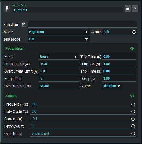
Functions | Shows the list of connected function(s). Multiple functions controlling one pin is not normally recommended. |
Mode | Sets pin mode
|
Status | Shows the current status of the pin, and may be used to control subsequent GP Logic, Math or GP Function blocks. |
Test Mode | Setting to a test mode (Active or PWM) will turn the output status to active and override any function using this pin.
|
Protection
Mode | Sets fuse mode
|
Inrush Limit + Trip Time + Duration | When the pin switches active, the 'Inrush Limit' will be used for the 'Duration' period. The output will go into a fault state if it exceeds the 'Inrush Limit' for longer than the 'Trip Time'. When configured as a half/full bridge, 'Duration' is disabled. The Inrush Limit will be continuously monitored. |
Overcurrent Limit + Trip Time | Normal fuse trip current in Amps. If a current value higher than 'Overcurrent Limit' is detected for longer than the 'Trip Time' period, the pin will enter a Fault state. If configured as a high/low side driver, the 'Overcurrent Limit' will only be used after the 'Inrush Duration' has finished. |
Retry Limit + Delay | Retry Counter. With 'Retry' Protection Mode enabled, and under fault conditions, the pin will attempt to switch Active, up to 'Retry Limit' times. After 'Retry Limit' attempts, the pin will remain Inactive until a setting is changed or the next power cycle. |
Over-Temp Limit | If the PDM reaches an internal temperature greater than the 'Over-Temp Limit', this pin will go into the Fault state. This feature is used to perform staged thermal shutdown on a pin-by-pin basis, typically activated only for low-priority output pins. |
Safety | Set whether or not this output can be turned off by the Safety Override.
|
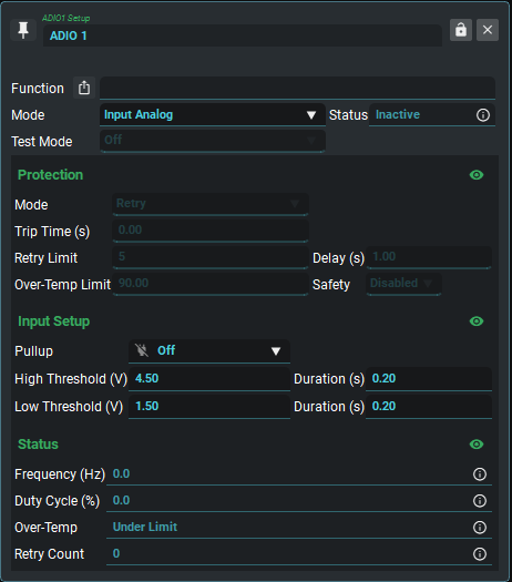
ADIO Pins
ADIO Input Mode Configuration
ADIO Output Mode Configuration
Functions | Shows the list of connected function(s). Multiple functions controlling one pin is not normally recommended |
Mode | Sets pin mode
|
Status | The status output shows the current status of the pin, and may be used to control subsequent GP Logic, Math or GP Function blocks. |
Test Mode | Setting to a test mode (Active or PWM) will turn the output status to active and override any function using this pin.
|
Protection - Active only in Output Mode
Mode | Sets fuse mode
|
Trip Time | Fuse trip timing in seconds. When the pin switches to active, if a current value higher than 8A is detected for longer than the 'Trip Time' period, the pin will enter a Fault state |
Retry Limit | Retry counter. With 'Retry' Fuse Mode enabled, and under fault conditions, the pin will attempt to switch Active, up to 'Retry Limit' times. After 'Retry Limit' attempts, the pin will remain Inactive until a setting is changed or the next power cycle |
Delay | Retry delay. With 'Retry' Fuse Mode enabled, and under fault conditions, the pin will wait for 'Delay' seconds before trying to switch active again. |
Over-Temp Limit | If the PDM reaches an internal temperature greater than the 'Over-Temp Limit', this pin will go into the Inactive state. This feature is used to perform staged thermal shutdown on a pin-by-pin basis, typically activated only for low-priority output pins. |
Safety | Set whether or not this output can be turned off by the Safety Override.
|
Input Setup - Active only in Input Mode
Pullup | Enables an internal 4.7k pullup resistor, to sensor 5V. |
High Threshold + Duration | When the pin voltage exceeds Threshold High (V) for at least Duration (s), the pin state is set to Active. ⭐When an ADIO is set as an output, the input voltage is fixed at 0V. |
Low Threshold + Duration | When the pin voltage is less than Threshold Low (V) for at least Duration (s), the pin state is set to Inactive. ⭐When an ADIO is set as an output, the input voltage is fixed at 0V. |