Auto Control Initial Setup
Accessing settings
To access Auto Control settings, your ECU needs to be running:
G4X: Firmware version 6.30.2 or newer
G5: Firmware version 7.7.2 or newer
Settings are under Chassis and Body→Automatic control. Some settings also exist under Chassis and Body→Gear Detection.
Initial setup
Mode
Under the Chassis and Body→Automatic Control settings, select Mode, and chose your transmission model. Refer to the help file in PCLink to find out which transmission model is applicable to you.
This will set things up automatically such as the shift solenoid pattern/logic, and things like overrunning clutch solenoids when applicable.
Assiging Pins
You will need to have on hand how you have wired your transmission up to your Link ECU.
Go through each setting tree relating to each input and output, and enter the details for your particular install.
If you need to control accessories such as 4WD lock up or torque split, the current method is to control these solenoids with a GP PWM, which you can setup up with your own desired axis, such as Vehicle Speed vs TPS, or a %slip between front and rear if you have these run times available to you.
GP PWM tables allow you to use any runtime, including other table outputs, or mathblocks on the axis, allowing you to be very creative with how you can run these solenoids.
Gear Detection
There are multiple different ways the various transmissions we support detect what gear position the selector is in. Read the help manual in PCLink for more detailed information on how to set this up.
The software also has provisions for retrofitting manual shifting, so be sure to read that section of the help file, even if your transmission did not have a manual mode from factory, it may be possible to retrofit.
Some tiptronic/sport shift gearboxes have additional hardware or different valve bodies for manual shifting. Adding manual shifting to older non Tiptronic transmissions will not result in faster shifts, due to the lack of this hardware. Sometimes these manual shifts in can take over a second between the shift being commanded, and the shift physically occurring, this is just a reality of older hardware.
Gear ratios
Gear ratios for some transmissions supported by Auto Control are listed in the help file. If they are not, you can usually find these listed in factory service manuals, or online in databases.
You can enter gear ratios under Chassis and Body→Gear Detection→Gear Ratio Table
With RPM Speed Source Auto Control, you must have the transmissions actual gear ratios entered, and use the gear normalise number to correct for road speed. TC Slip will be calculated when your output shaft speed is correctly calibrated.
Shift Tables
For the initial tune, it’s best to stick with 1 table.
For each shift “table”, there is an UpShift table, and a DownShift table. Most setups will be speed/tps based, though you can customise the axis' to your liking.
If you have data on the factory shift tables, it’s a good idea to start with these, and modify to suit. Below is an example of a BC/BF Subaru Legacy shift table, for reference on what a shift table can look like.
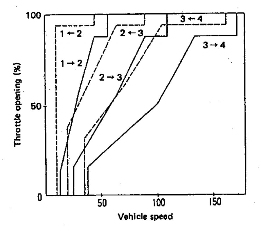
These tables can be difficult to fathom at first, so we suggest plotting them on graphing or spreadsheet software, to display them in a similar way to above, to see how the two tables interract. It’s important that you do not cross the shift lines between a given upshift point, and downshift point. I.e. you shouldn’t have your 2-3 shift line cross below the 3-2 shift line at any point. If you do, you’ll be commanding both an up and a downshift simultaneously. In this case the software will do nothing until only one shift is being commanded.
Force Upshift
Some factory TCUs will force an upshift at a set RPM to prevent the engine from hitting the rev limiter. Others don’t force an upshift at all, allowing the engine to reach the limiter.
To replicate the latter behaviour, simply set the force upshift RPM higher than the rev limiter.
The X axis on the force upshift table is ECT (Engine Coolant Temperature), since it’s common practice in aftermarket tuning to use lower rev limits at lower ECTs. Because of this, it’s possible that during warm-up, the normal commanded shift RPM might sit above the rev limit for that temperature range.
In these cases, you can set the force upshift RPM slightly below the rev limit while the engine is cold. This prevents the transmission from holding the engine on the limiter while waiting for a shift point above said limiter.
In older transmissions, set the RPM 500-1000 rpm lower than you want, to account for the long shift times these transmissions can have.
Line Pressure
How Line Pressure Works
Line pressure is the hydraulic pressure used throughout the transmission to actuate clutch packs and bands. In the most basic of terms, this is the pressure which each solenoid in the transmission is allowing to act on their respective components, in reality it is often more complicated than this.
Line pressure is how we tune how smooth or harsh shifts can be, though is also how we can ensure the transmission won’t slip going into gear. In other words, it not only affects how quick or harshly clutches and bands actuate, but also how much clamping pressure is applied during and after the shift is complete.
Note some supported transmissions do not have solenoid controllable line pressure
In most transmissions, duty% is inversely proportional to line pressure, as the solenoids are usually set up to bleed line pressure off.
Also with most transmissions, the amount of pressure the Line Pressure Solenoid can bleed off is often limited, with a base amount of pressure going to the solenoids even if fully bled off. It’s not unusual to see a base line pressure of several hundred kpa, which is always there regardless of Line Pressure Duty. This becomes relevant as you fine tune line pressures later.
If you do not have any data on how factory line pressure is set up, avoid putting excess torque through the transmission until you establish what duty% gives you what line pressures. Failure to do this can result in clutch pack or band damage.
Setting Up Line Pressure
Once you have assigned the output for this, you’ll have access to the Line Pressure DC Table and Line Pressure Shifting DC Table. It’s best to start here with a duty that delivers higher line pressure across the board, in both tables.
For initial tuning, set both the DC Table, and Shifting DC Table to the same values.
It is also possible to setup closed loop line pressure, even if your transmission did not have it from factory. Many transmissions have test ports used for diagnostics which you can install a pressure sensor in. Be aware pressures can get over 1000kpa/150psi, so be sure to select an appropriate sensor.
Torque Converter Lockup
During your first test drives, you will need to be able engage the torque converter lockup in all gears to calibrate your gear ratios, so we need to set this up now.
For initial setup, you can set a slow ramp in over a long period of time. Later during the tuning process, you can refer to logs to tighten up TC Lockup duties and timing for quick TC lockup.
It is also useful to set up a force enable input for testing, for the gear ratio calibration.
First Test Drive.
With these settings entered, you can proceed to go for the first test drive.