Installation
Mounting
The DI Driver is mounted using two M5 socket head cap screws.
The DI Driver-4 will generate heat during operation. Keeping temperature within operational limits should be considered when mounting. Minimizing the loom length should also be considered.
Wiring
The DI Driver-4 uses a 26 pin super seal connector with the ‘D' key positions. The pin locations are shown in the image below and the purpose of each pin is explained below. Injectors 1A&1B as well as 2A&2B are paired on the high side output. This means it’s critical that each injector they drive is half an engine cycle apart from each other.
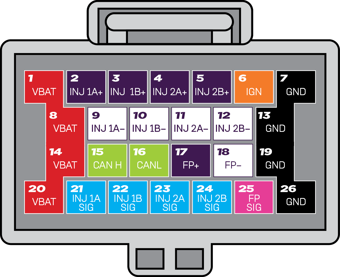
DI Driver-4 pinout looking into back of connector
VBat (x4) - These are the power supply pins, connect these to power feed capable of supplying 20A. The DI Driver-4 requires quite a large amount of power as it is boosting the voltage and controlling high current injectors and pump solenoids.
GND (x4) - These are the power ground pins, connect these to a chassis ground capable of sinking 25A.
IGN - This is the ignition power pin to turn on the DI Driver-4. Connect this pin to an ignition switched power supply that can supply 0.5A. Note you can power up and configure the device using the USB port but it will not control injectors or pumps without the main header power and ground pins being connected and the ignition switch being powered.
CANH and CANL - The CAN bus in this device can be used to feed various runtime values and statuses back to the ECU allowing the controlling ECU to throw fault codes in the event the DI Driver-4 encounters a fault.
Inj1A, 1B,2A & 2B Sig - These pins are the injector inputs from the ECU, they can be configured to accept active low or active high signals, make sure this is configured correctly in both the ECU and this device before powering it on to prevent a constantly on injector issue.
FP Sig - This pin is the Fuel Pump Solenoid input from the ECU, it can be configured to accept active low or active high signals, make sure this is configured correctly in both the ECU and this device before powering it on to prevent a constantly on pump solenoid issue.
INJ1A+, 1B+,2A+, 2B+ and INJ1A-, 1B-, 2A-, 2B- - Connect these pins to the appropriate injector, one ‘-' pin and the matching ‘+’ pin per injector. Note the injector’s boost power is connected in pairs with INJ1A & INJ1B having the same supply and INJ2A & INJ2B having the same supply so they should be wired so that the injection order alternates between one from one pair, one from the other, the other from the first pair and then the other from the second pair.
FP- and FP+ - Connect these pins to the High Pressure Fuel Pump solenoid.
Recommended Wiring
Below are recommended wiring layouts for 4, 6 and, 8 cylinder engines. These recommendations are based on the requirement that each set of paired injector drives, be half an engine cycle apart.
3 Cylinder Pinouts:
With 3 cylinders in a 4 stroke engine the maximum distance between any two cylinders firing is 240 degrees. This will limit the maximum injector duty cycle to 33%
3 Cyl with firing order 1-2-3 or 1-3-2 | |||
|---|---|---|---|
Engine Injector | ECU Injector Drive | DI Driver-4 Box | DI Driver-4 Box Input/Output |
Cyl 1 | Inj 1 | BOX 1 | 1A |
Cyl 2 | Inj 2 | BOX 1 | 2A |
Cyl 3 | Inj 3 | BOX 1 | 1B |
4 Cylinder Pinouts:
4 Cyl with firing order 1-3-4-2 | |||
Engine Injector | ECU Injector Drive | DI Driver-4 Box | DI Driver-4 Box Input/Output |
Cyl 1 | Inj 1 | BOX 1 | 1A |
Cyl 2 | Inj 2 | BOX 1 | 2B |
Cyl 3 | Inj 3 | BOX 1 | 2A |
Cyl 4 | Inj 4 | BOX 1 | 1B |
4 Cyl with firing order 1-3-2-4 | |||
Engine Injector | ECU Injector Drive | DI Driver-4 Box | DI Driver-4 Box Input/Output |
Cyl 1 | Inj 1 | BOX 1 | 1A |
Cyl 2 | Inj 2 | BOX 1 | 1B |
Cyl 3 | Inj 3 | BOX 1 | 2A |
Cyl 4 | Inj 4 | BOX 1 | 2B |
6 Cylinder Pinouts:
6 Cyl with firing order 1-2-3-4-5-6 | |||
Engine Injector | ECU Injector Drive | DI Driver-4 Box | DI Driver-4 Box Input/Output |
Cyl 1 | Inj 1 | BOX 1 | 1A |
Cyl 2 | Inj 2 | BOX 2 | 1A |
Cyl 3 | Inj 3 | BOX 1 | 2A |
Cyl 4 | Inj 4 | BOX 1 | 1B |
Cyl 5 | Inj 5 | BOX 2 | 1B |
Cyl 6 | Inj 6 | BOX 2 | 2A |
6 Cyl with firing order 1-4-2-5-3-6 | |||
Engine Injector | ECU Injector Drive | DI Driver-4 Box | DI Driver-4 Box Input/Output |
Cyl 1 | Inj 1 | BOX 1 | 1A |
Cyl 2 | Inj 2 | BOX 1 | 2A |
Cyl 3 | Inj 3 | BOX 2 | 1B |
Cyl 4 | Inj 4 | BOX 2 | 1A |
Cyl 5 | Inj 5 | BOX 1 | 1B |
Cyl 6 | Inj 6 | BOX 2 | 2A |
6 Cyl with firing order 1-5-3-6-2-4 | |||
Engine Injector | ECU Injector Drive | DI Driver-4 Box | DI Driver-4 Box Input/Output |
Cyl 1 | Inj 1 | BOX 1 | 1A |
Cyl 2 | Inj 2 | BOX 2 | 1B |
Cyl 3 | Inj 3 | BOX 1 | 2A |
Cyl 4 | Inj 4 | BOX 2 | 2A |
Cyl 5 | Inj 5 | BOX 2 | 1A |
Cyl 6 | Inj 6 | BOX 1 | 1B |
8 Cylinder Pinouts:
8 Cyl with firing order 1-3-2-5-8-6-7-4 | |||
Engine Injector | ECU Injector Drive | DI Driver-4 Box | DI Driver-4 Box Input/Output |
Cyl 1 | Inj 1 | BOX 1 | 1A |
Cyl 2 | Inj 2 | BOX 1 | 2A |
Cyl 3 | Inj 3 | BOX 2 | 1A |
Cyl 4 | Inj 4 | BOX 2 | 2B |
Cyl 5 | Inj 5 | BOX 2 | 2A |
Cyl 6 | Inj 6 | BOX 2 | 1B |
Cyl 7 | Inj 7 | BOX 1 | 2B |
Cyl 8 | Inj 8 | BOX 1 | 1B |
8 Cyl with firing order 1-3-7-2-6-5-4-8 | |||
Engine Injector | ECU Injector Drive | DI Driver-4 Box | DI Driver-4 Box Input/Output |
Cyl 1 | Inj 1 | BOX 1 | 1A |
Cyl 2 | Inj 2 | BOX 2 | 2A |
Cyl 3 | Inj 3 | BOX 2 | 1A |
Cyl 4 | Inj 4 | BOX 1 | 2B |
Cyl 5 | Inj 5 | BOX 2 | 1B |
Cyl 6 | Inj 6 | BOX 1 | 1B |
Cyl 7 | Inj 7 | BOX 1 | 2A |
Cyl 8 | Inj 8 | BOX 2 | 2B |
8 Cyl with firing order 1-5-4-2-6-3-7-8 | |||
Engine Injector | ECU Injector Drive | DI Driver-4 Box | DI Driver-4 Box Input/Output |
Cyl 1 | Inj 1 | BOX 1 | 1A |
Cyl 2 | Inj 2 | BOX 2 | 2A |
Cyl 3 | Inj 3 | BOX 2 | 1B |
Cyl 4 | Inj 4 | BOX 1 | 2A |
Cyl 5 | Inj 5 | BOX 2 | 1A |
Cyl 6 | Inj 6 | BOX 1 | 1B |
Cyl 7 | Inj 7 | BOX 1 | 2B |
Cyl 8 | Inj 8 | BOX 2 | 2B |
8 Cyl with firing order 1-5-4-8-6-3-7-2 | |||
Engine Injector | ECU Injector Drive | DI Driver-4 Box | DI Driver-4 Box Input/Output |
Cyl 1 | Inj 1 | BOX 1 | 1A |
Cyl 2 | Inj 2 | BOX 2 | 2B |
Cyl 3 | Inj 3 | BOX 2 | 1B |
Cyl 4 | Inj 4 | BOX 1 | 2A |
Cyl 5 | Inj 5 | BOX 2 | 1A |
Cyl 6 | Inj 6 | BOX 1 | 1B |
Cyl 7 | Inj 7 | BOX 1 | 2B |
Cyl 8 | Inj 8 | BOX 2 | 2A |
8 Cyl with firing order 1-8-4-3-6-5-7-2 | |||
Engine Injector | ECU Injector Drive | DI Driver-4 Box | DI Driver-4 Box Input/Output |
Cyl 1 | Inj 1 | BOX 1 | 1A |
Cyl 2 | Inj 2 | BOX 2 | 2B |
Cyl 3 | Inj 3 | BOX 2 | 2A |
Cyl 4 | Inj 4 | BOX 1 | 2A |
Cyl 5 | Inj 5 | BOX 2 | 1B |
Cyl 6 | Inj 6 | BOX 1 | 1B |
Cyl 7 | Inj 7 | BOX 1 | 2B |
Cyl 8 | Inj 8 | BOX 2 | 1A |
8 Cyl with firing order 1-8-7-2-6-5-4-3 | |||
Engine Injector | ECU Injector Drive | DI Driver-4 Box | DI Driver-4 Box Input/Output |
Cyl 1 | Inj 1 | BOX 1 | 1A |
Cyl 2 | Inj 2 | BOX 2 | 2A |
Cyl 3 | Inj 3 | BOX 2 | 2B |
Cyl 4 | Inj 4 | BOX 1 | 2B |
Cyl 5 | Inj 5 | BOX 2 | 1B |
Cyl 6 | Inj 6 | BOX 1 | 1B |
Cyl 7 | Inj 7 | BOX 1 | 2A |
Cyl 8 | Inj 8 | BOX 2 | 1A |
CAN Wiring
CAN ID supports normal format only (not extended) and so a max ID of 2047 is possible.
The DI Driver-4 will communicate with multiple devices connected to the same CAN bus. The CAN bus should be wired according to CAN requirements.

USB Connection
The DI Driver-4 can be connected to a PC via USB C. The USB cable will power the DI Driver-4 to allow configuration of the DI Driver-4 without having VBAT, GND and IGN connected.
The injector and fuel pump inputs and outputs can be configured, but will not operate when the DI Driver-4 is powered only by USB