Configuration
Software and Firmware
DI Link software can be downloaded at linkecu.com/software-support/. Keep checking for updates to ensure you're using the latest release.
Firmware comes bundled with the DI Link application. Ensure you have downloaded the latest DI Link software and installed this on your PC before performing a firmware update
To update firmware on the DI Driver-4 follow the steps below:
Connect the DI Driver-4 to a PC using the supplied USB-C cable
Select Menu>DI Driver>Update Firmware
Click the 3 dot icon, and navigate to:
C:\Program Files (x86)\DILink\Resources\Firmware\?????-firmware.img
Select the latest version and select Open. This will populate the Upgrade Firmware menu with all versions in the folder
Highlight the latest version and select START
The Software and Firmware versions can be found by selecting Menu>Help>About.
Boost Converter
Converter - This setting global enables or disables the boost converter. This should be left enabled for most use cases.
Temp Limit - This setting is the maximum temperature under which the boost converter will remain running. If the measures heat sink temperature exceeds this temperature the boost converter and injectors are shutdown. Once the temperature falls below this set value the boost converter and injectors will resume operation.
Voltage (V) - This setting controls the voltage that is output during the boost phase of the injection. This value, the Boost Current value and the resistance and inductance characteristics of the injector determine how long the boost phase will take.
Injector Settings
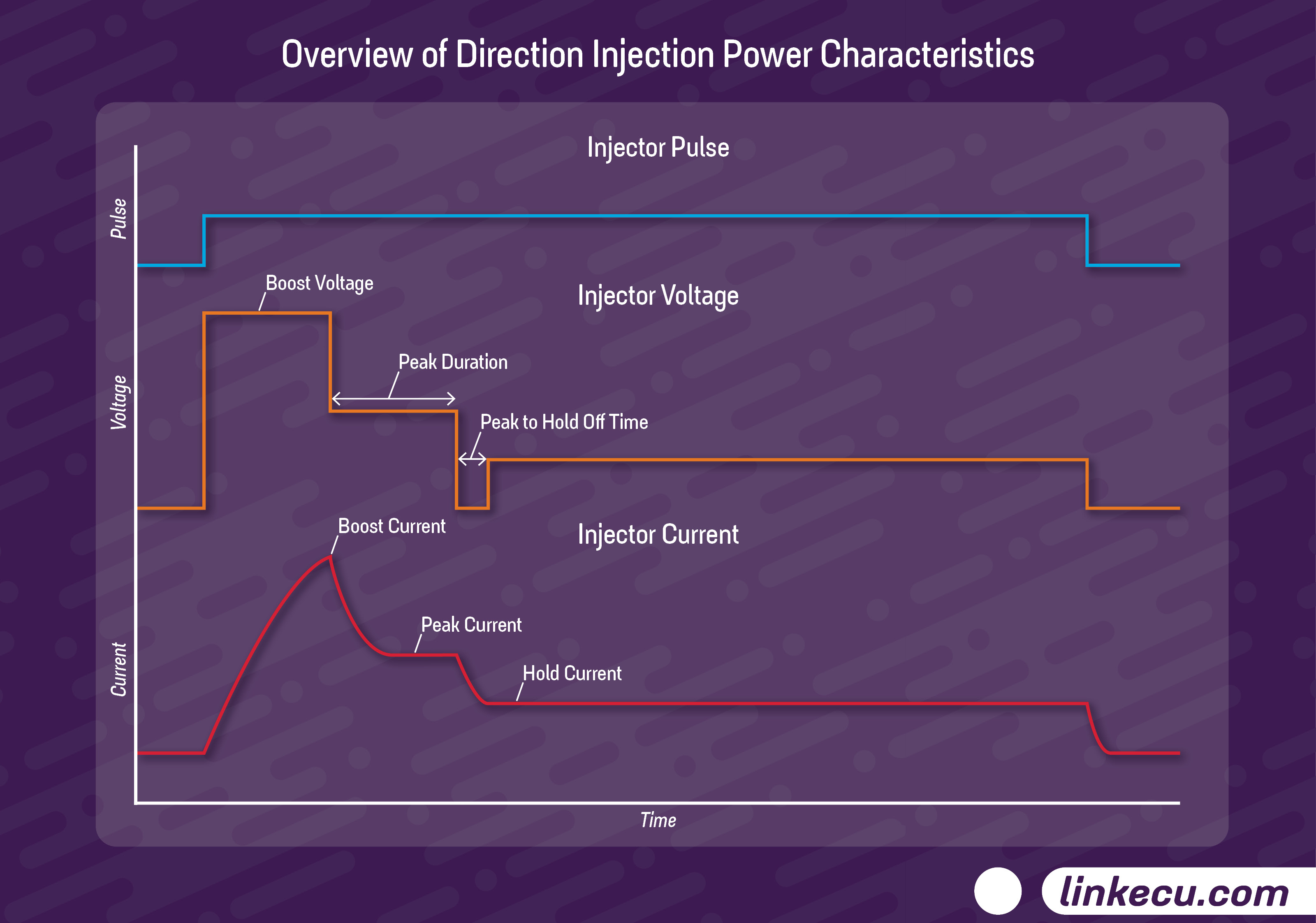
Injection pulses consist of several parts, an initial boost phase, a peak or pull-in phase, a peak holdoff time and then a hold phase.
In the boost phase the Boost Voltage value is applied to the injector until the Boost Current value is reached. The length of this phase is dependent on the Boost Voltage, Boost Current and inductive and resistive characteristics of the injector. A higher Boost Voltage or lower Boost Current will result in a shorter boost phase and a lower Boost Voltage or higher Boost Current will result in a longer boost phase.
If the current rises to fast in the boost phase then a fault is thrown. This will be interpreted as a short circuit by the DI Driver. If the Boost Current cannot be reached - within the entire injection pulse width time then a fault code will be thrown. This means that your minimum pulse width in the ECU should be set appropriately to avoid this.In the peak, or pull-in, phase the power is turned off allowing the current to drop away rapidly until it reaches the Peak Current value. Once the Peak Current value has been reached it is held at that current by PWM control of battery voltage until the Peak Duration time is reached.
If the Peak Duration is set too short the current won’t drop far enough to need to be held up and the hold phase will be entered with a higher current value than the Peak Current value.
If the Peak Current is higher than can be reached with battery voltage across the injector then the output will be held on at battery voltage until the Peak Duration has passed.
To Clarify the Peak Duration time starts as soon as the boost phase finishes NOT when the Peak current is reached.Once the Peak duration has been reached the output is turned off for the duration of the Peak Holdoff Time. This time with the output off allows the voltage to rapidly drop prior to the hold phase starting.
If the Peak Holdoff Time is too long then the current will drop below the hold amount prior to the hold starting, if it is too short then the current will be higher than the hold current when the hold phase begins. The correct value will depend on the peak current, hold current and injector characteristics.Once the Peak Holdoff Time has passed the hold phase starts. The hold phase consists of the output PWMing battery voltage to try and maintain the specified hold current and this phase continues until the end of the injector input signal into the DI driver box.
Injector Type - User defined/Other options. This sets the injector settings either to a preconfigured set from Link or allows a user defined set to be entered. When this is set to a preset setup (not User defined), changes made to injector setup values will not persist after a power cycle.
Boost Current (A) - This setting controls the target current during the boost phase of the injection, once this current is reached the boost voltage is turned off and the peak (also known as pull-in) phase of the injection begins. This value, the Boost Voltage value and the resistance and inductance characteristics of the injector determine how long the boost phase will take.
Peak Current (A) - This setting determines the target current output during the peak (also known as pull-in) phase and the DI driver box will PWM battery voltage in order to obtain this Peak Current value.
Peak Duration (µs) - This setting controls the length of the peak phase, this time starts as soon as the Boost Voltage is turned off and once it ends the output is turned off and the Peak Holdoff Time begins.
Peak Holdoff Time (µs) - This setting controls how long the output is turned off between the peak (also known as pull-in) phase ending and the hold phase starting. If this time is too long then the current will drop below the hold amount prior to the hold phase starting.
Hold Current (A) - This setting determines the target current output during the hold phase and the DI driver box will PWM battery voltage in order to obtain this Hold Current value.
Polarity - This setting controls whether the INJ1x SIG pins are considered active (and so the matching output should be turned on) when the input is High or when the input is Low. Standard port injectors are active when the ECU output is low but OE devices like the GT86 DI Driver is active when the ECU output is high like a standard smart coil drive. This setting must match how the ECU is configured or the injector outputs will be on while the ECU is not commanding a pulse and vice versa possibly causing engine damage.
Fuel Pump Settings
Fuel Pump Type - User defined/Other options. This sets the fuel pump settings either to a preconfigured set from Link or allows a user defined set to be entered. When this is set to a preset setup (not User defined), changes made to fuel pump setup values will not persist after a power cycle.
Peak Current (A) - This setting determines the target current output during the peak phase of the fuel pump output and the DI driver box will PWM battery voltage in order to obtain this Peak Current value.
Peak Duration (µs) - This setting controls the length of the peak phase, this time starts as soon as the FP SIG input is becomes active and once it ends the output is turned off and the FP Peak Holdoff Time begins.
Peak Holdoff (µs) - This setting controls how long the fuel pump output is turned off between the peak phase ending and the hold phase starting. If this time is too long then the current will drop below the hold amount prior to the hold phase starting.
Hold Current (A) - This setting determines the target current output during the hold phase and the DI driver box will PWM battery voltage in order to obtain this FP Hold Current value.
Polarity - This setting controls whether the FP SIG pin is considered active (and so the fuel pump output should be turned on) when the input is High or when the input is Low. This setting must match how the ECU is configured or the fuel pump output will be on while the ECU is not commanding a pulse and vice versa possibly causing engine damage.
Device Status
Battery Voltage (V) - This shows the current battery voltage on the VBAT input pins.
Ignition SW Voltage (V) - This shows the current voltage on the Ign input pin.
Heat Sink Temperature (°C) - This shows the temperature of the heat sink mounted thermocouple
Internal Temperature (°C) - This shows the temperature of the embedded micro thermocouple
Drive Status
This is a collection of statuses and runtimes that indicate any faults that have been detected in either the Injectors, Fuel pump or boost converter.
Injectors
Status: | Normal | Fault |
|---|---|---|
Inj 1A&1B HS Short Inj 2A&2B HS Short | Operating correctly | Excessive current was drawn from the corresponding positive pins |
Inj 1A&1B Wiring | Operating correctly | An open circuit or short to ground has been detected on the corresponding positive pins |
Inj 1A LS Short | Operating correctly | Injector driver detected a short circuit from the negative pins to either |
Inj 1A Time-out | Operating correctly | The injector was asked to turn on for an unusually long pulse width |
Fuel Pump
Fuel Pump Wiring Status | Operating correctly | An open circuit or short to ground was detected |
Fuel Pump Short Status | Operating correctly | A short circuit was detected |
Fuel Pump Time-out Status | Operating correctly | An unusually long pulse was requested |
Boost Converter
DCDC % Active - Percent of total operating time the DC-DC boost converter is operating. This gives an indication of the current load on the DI Driver. If this value hits 100% the DI Driver will fail to operate correctly
Disable | Enable | |
|---|---|---|
Boost Drive | The boost converter is disabled and won’t operate | The boost converter is enabled and will operate |
Charging | Ready | |
|---|---|---|
Boost Voltage | The boost converter hasn’t reached target voltage | The boost convert has reached target voltage |
Normal | Fault | |
|---|---|---|
Boost Undervoltage | Operating correctly | The boost converter has failed to maintain boost voltage |
CAN Settings
Transmit ID - The ID the fixed CAN stream should transmit on.
Terminator - Software configurable CAN bus termination resisitor
Bus Frequency (bps) - The data rate the CAN bus is operating at. The standard rate for aftermarket use is 1M
Transmit Period (ms) - Time between each message of the fixed CAN stream.
CAN Stream
The DI Driver-4 transmits a fixed CAN stream that other devices to review and report on the status of any DI Driver. This could be used to trigger a check engine light if needed, or monitor temperatures.
Byte 0 | Byte 1 | Byte 2 | Byte 3 | Byte 4 | Byte 5 | Byte 6 | Byte 7 |
|---|---|---|---|---|---|---|---|
Number of faults | 1A&1B faults | 2A&2B faults | Reserved | Fuel Pump faults | DC-DC% Active | Batt Volt | Heat Sink Temperature |
Number of faults - The total number of reported faults present on the DI Driver.
1A&1B faults - A bit mask of the faults present for injector 1A&1B. These faults are counted in the number of faults above. These faults are ‘sticky’ meaning that once a faults has occurred the value won’t clear until a power cycle of the DI Driver.
2A&2B faults - A bit mask of the faults present for injector 2A&2B. These faults are counted in the number of faults above. These faults are ‘sticky’ meaning that once a faults has occurred the value won’t clear until a power cycle of the DI Driver.
CAN Injector Faults | ||
Individual Value | Fault | |
Bit 0 | 1 | Low Side Short A |
Bit 1 | 2 | Low Side Short B |
Bit 2 | 4 | Timeout A |
Bit 3 | 8 | Timeout B |
Bit 4 | 16 | High Side Short |
Bit 5 | 32 | Wiring Fault |
Fuel Pump faults - A bit mask of the faults present for the fuel pump. These faults are counted in the number of faults above. These faults are ‘sticky’ meaning that once a faults has occurred the value won’t clear until a power cycle of the DI Driver.
CAN Fuel Pump Faults | ||
|---|---|---|
Individual Value | Fault | |
Bit 0 | 1 | Short |
Bit 1 | 2 | Timeout |
Bit 2 | 4 | Wiring Fault |
DC-DC% Active - The percent of time the DC-DC boost converter is operating.
Batt Volt - The battery voltage. This has a multiplier of 10x
Heat Sink Temperature - The current heat sink temperature in Celsius. This has an offset of +50.
Visualizations
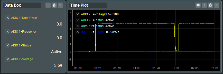
Data Monitors
Data monitoring visualizations can be found live, by either right-clicking or double clicking the background.
Stretch Lists Traffic Light indicators Bar Gauges

Vertical Lists Time Plots
Text Memos
Memos can be added to any to any tab - as many as you want. Right-click, or Double click the background, to add a new memo box.
Memos are stored in saved in DILink configuration files (.dic)