G5 Voodoo Neo Pinouts
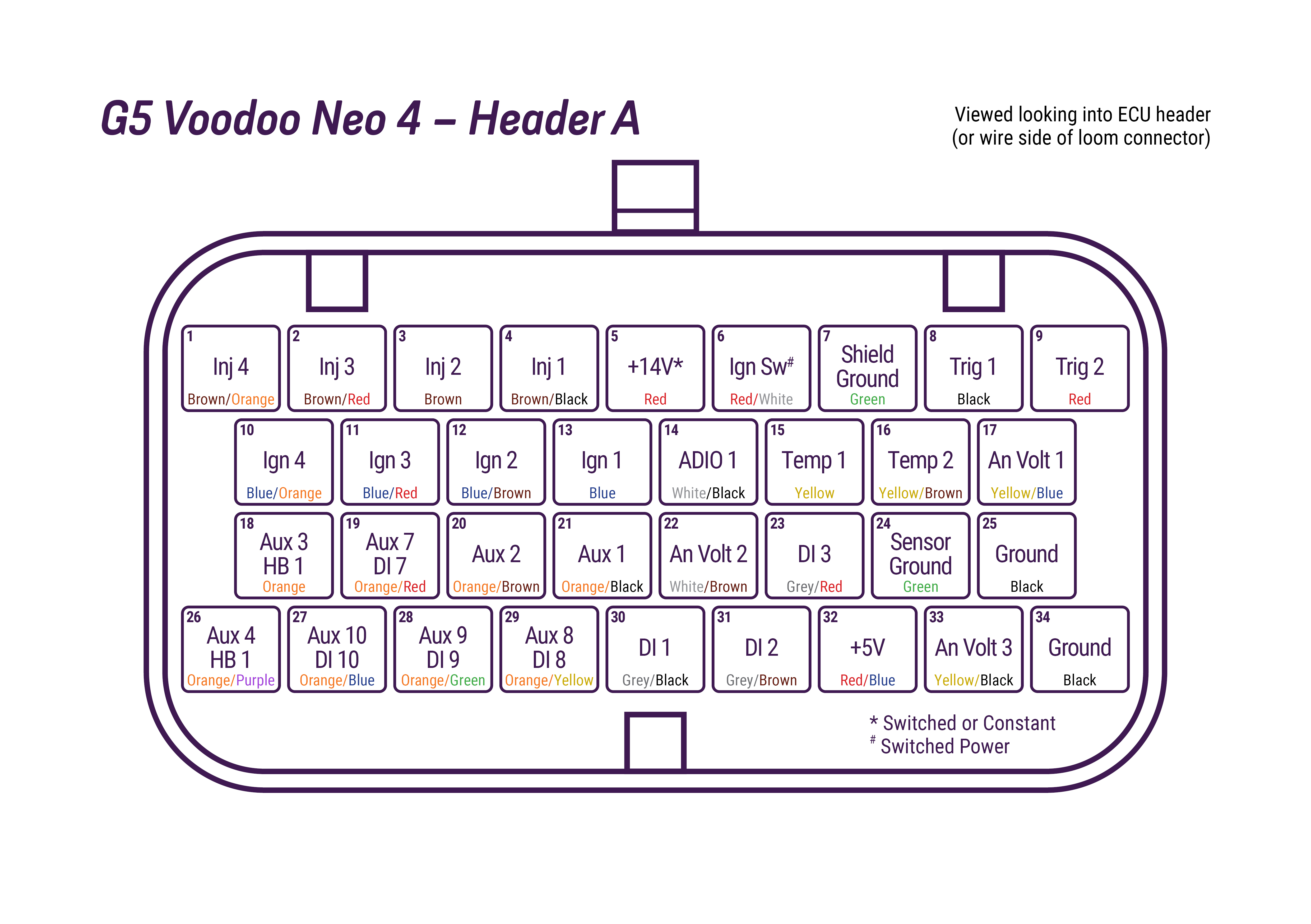
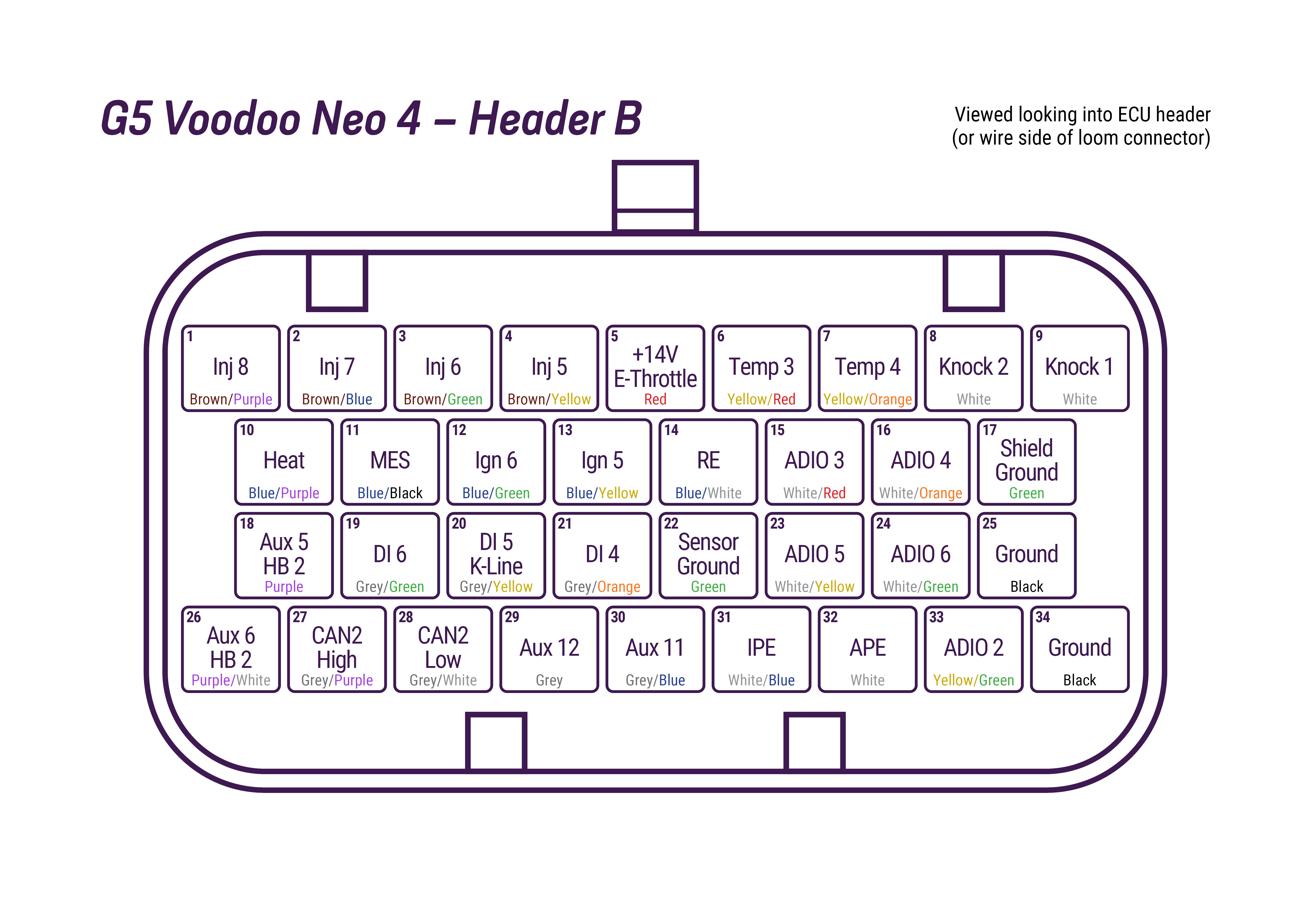
Neo 4 Pinout
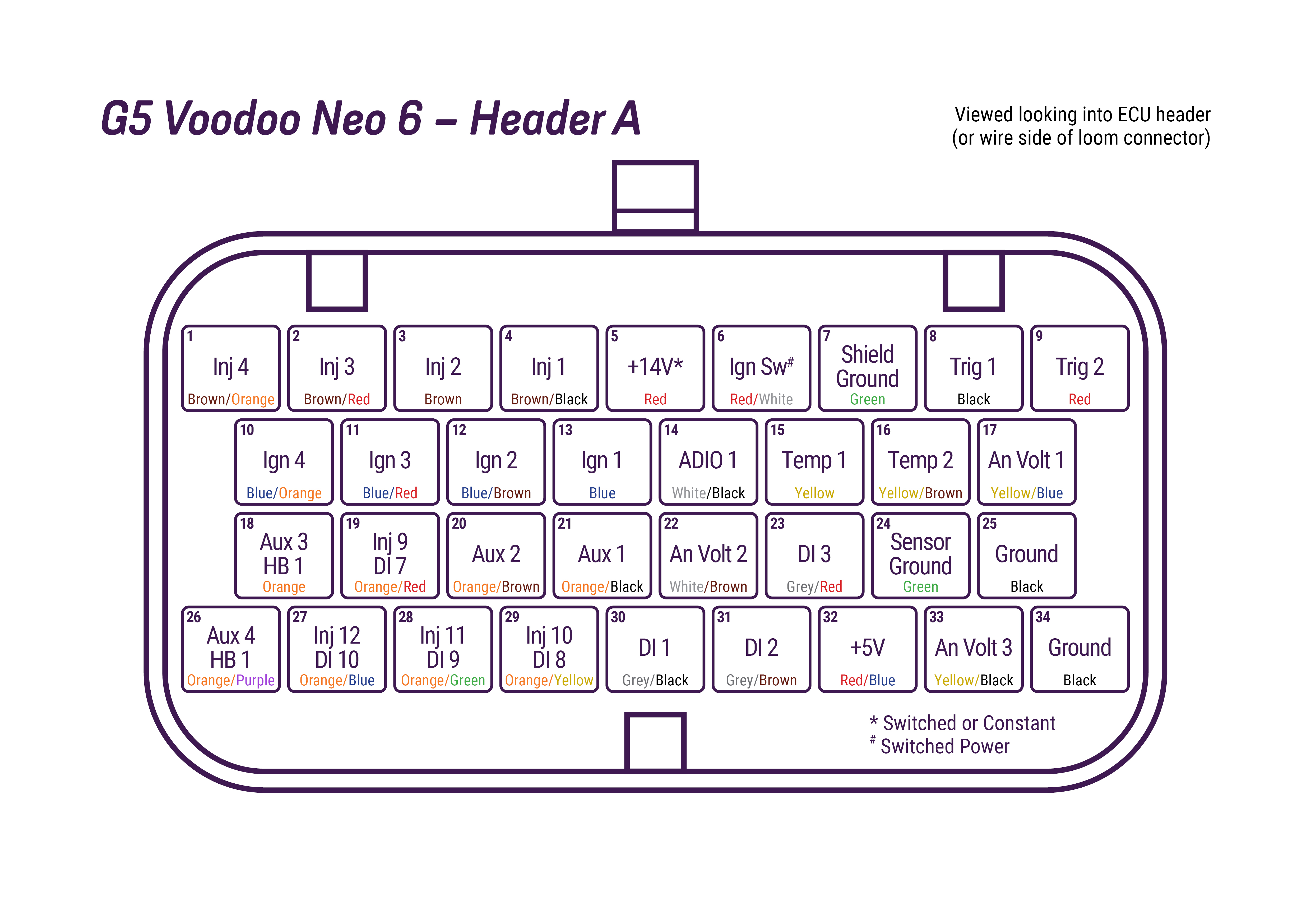
Neo 6 Pinout
A-Header | B-Header |
 |  |
A-Header | B-Header |
 |  |
Notes for wiring
Power
Pin A5 is the main ECU power input. It can be supplied with either switched or constant VBat.
Pin A6 is the ignition switch input. It must be connected to a switched battery source. The ECU will not power down if A6 is connected to constant VBat.
Pin B5 needs to be supplied VBat to power the H-Bridge drivers (AUX3/4/HB1 and AUX5/6/HB2). These drives will not function if B5 is unpowered.
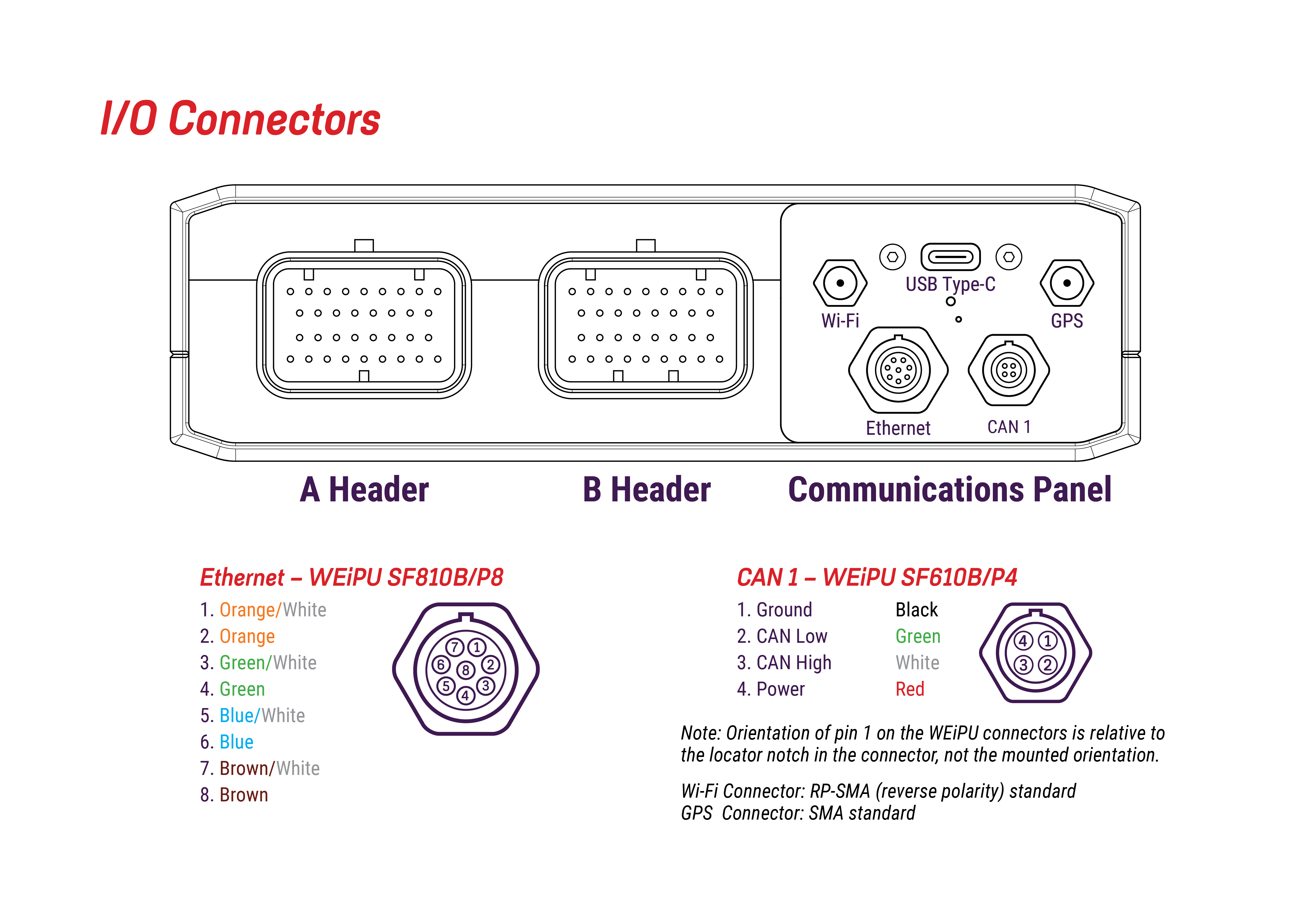
CAN 1 has a +14V 3A cont. power output from the ECU for the CAN Bus. CAN 1 power out is sufficient to power a CAN Lambda.
The ECU can be partially powered up over USB-C Power, enough to connect to PC Link, change settings, download logs, perform firmware updates etc. Not all hardware functionality will be available while on USB power though, for example Analog Voltages will show 0V and output statuses will show 'Off'. When powered by USB, rather than main ECU power, the connected status in PC Link will show blue, not green.
Grounding
Grounding of the ECU should always be done to a single common point on the engine block or heads to reduce any voltage potentials between sensors and ECU grounds, and prevent ground loops.
Failure to ground the ecu to the engine can introduce inaccuracies.
For any sensors with a ground pin on the sensor, only ground these to shield or sensor grounds on the ECU.
Ensure the engine is well grounded to battery negative.